Assignment
Date: 4/15/2005
Due Day:
Part 1 4/22/2005; Part 2 5/5/2005
For Part1, you can use the TinyOS installed in the xpvm1 virutal machine of your designated EAS 140 PCs (same as the one for hw2). You can also download it from http://www.tinyos.net/download.html to carry out the exercises at home. Note that the TinyOS version for XP is about 171MB. It includes the cygwin, a linux like environment for Windows. Try to use the cygwin that comes with the TinyOS distribution for compatibility.
Part 1. Familiar with TinyOS, TOSSIM, and TinyViz.
Assume you choose to carry out exercises using the xpvm1 in EAS 140 PC.
For part1 of hw1, we will get familar with the TinyOS compilation and simulator.
After relogin with "Edward Chow", click the Cygiwn icon on the top left corner. It will start a cygwin shell window. It starts with a bash shell. We will first add the path of a visual GUI tool called TinyViz to the PATH environment variable.
You can hit tab key to allow cygwin bash to complete the file/director name.
to back up the demo applications directory.
In apps directory there
are many sensor demo programs. Some are referenced in the TinyOS tutorial
http://www.tinyos.net/tinyos-1.x/doc/tutorial/index.html
Each directory contains the source code and Makefile. The makefile allows
option for generating the actual sensor code or for generating the simulated
version.
We will first try the run the Blink demo which turn on and off the red LED.
To compile a simulation version of the sensor application, type "
If you were to generate the actual sensor code, "make mica2" is used.
You will see the compilation process. At the end it will report the the size of the generated program both in terms of code and data size.
To run the simulator, first set the the envrionment variable which the simulator reads for generating certain diagnosis or simulation log. In our case, use
Since the simulated program are saved as build/pc/main.exe, let us start the program with
You will see the mesage similar to
0: LEDS: Red off
0: LEDS: Red on
...
Now let us start Lesson 5 of the tutorial.
See if you see the same messages in http://www.tinyos.net/tinyos-1.x/doc/tutorial/lesson5.html
Now let us try the TestTinyViz, which is sensor application used to demonstrate the TinyViz, a Java GUI for displaying the sensor simulation results.
Note that TinyViz is buggy as indicated by Philip Levis. If we follow the steps in Tutorial lesson 5,
We will get a Tinyviz
that only shows 30 sensors but does not animate the direct message sending
as a red lines.
To fix that let us follow the fix suggested by Philip Levis.
This will start the TestTinyViz with TOSSIM and wait for the GUI (TinyViz) program to connect/control through a socket.
In another cygwin
window,
PATH=/opt/tinyos-1.x/tools/java/net/tinyos/sim:$PATH
tinyviz
# this will start the TinyViz gui window.
In Plugins menu, select "radio link" and "debug message".
Click on the green playback button to start the simulation. If it shows
pause button, click it twice.
It should show the red line indicating the direct messages sent.
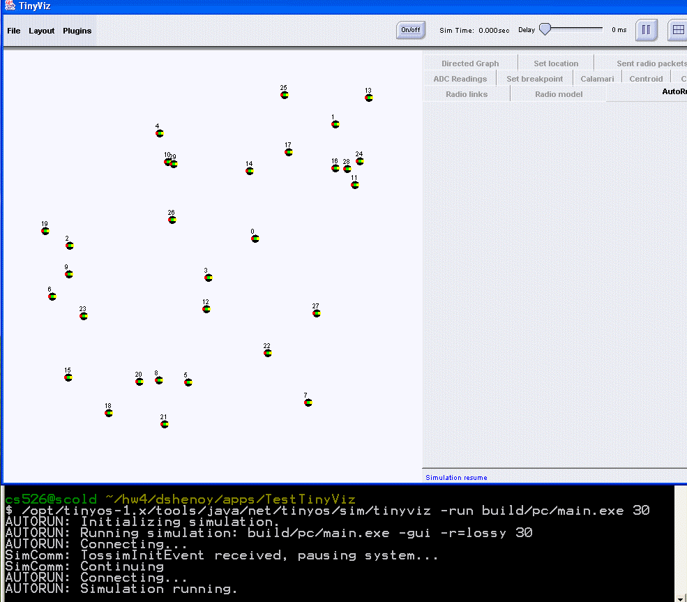
Capture the screendump
and save it as your part 1 of hw5. Here is an
TinyViz image I just captured.
You should see the java gui shows the random placement of the 30 sensors and when simulation started. Click the plugin menu and select the radio model. Then click on the sensor symbols. It will display the links to its neighbors and label them with signal strengths of the radio link.
Email me the url of the TinyViz image file as your part 1 submission.
Part 2. Mote Programming Exercise
For part 2, we will use the Crossbow Mica2 Mote Professional Development Kit in EAS 172 to carrry out the exercises in TinyOS Tutorials 1-4 with two additional exercises. Use the following reservation web page to reserve the one-hour time slot. http://cs.uccs.edu/~cs526/cgi-bin/reserve/wsnlab.htm
By doing that, ideally you only need to download those code from CS Unix machines to the EAS 172 laptop connected to MIB 500.
Here are list of exercises: