|
|Technical Manual | Software library | User's Guide | Troubleshooting | |
| IEEE 802.11 Industry overview Standards |
|
The IEEE 802.11 specification is a WLAN standard that
defines a set of specifications for physical layers (PHYs) and a medium
access control (MAC) layer. On the high-rate side, the 802.11b spec
defines a set of re-quirements for a new PHY as an ex-tension to the
legacy direct sequence spread spectrum (DSSS) PHY.
IEEE 802.11 MAC layer The MAC layer of the IEEE 802.11b specifications
handles many functions in a WLAN system. On one hand, the 802.11b MAC
layer (the second layer of the OSI model) serves as the interface between
the PHY and the host device. On the other, the MAC supports both ad-hoc
and client/server infrastructure networks. The IEEE 802.11b MAC layer is similar to the IEEE
802.3 Ethernet wired LAN standard. IEEE 802.3 Ethernet uses carrier sense
multiple access/collision detection (CSMA/CD) as its baseline protocol.
IEEE 802.11, however, employs carrier sense multiple access/collision
avoidance (CSMA/CA) as its protocol mechanism because it is difficult to
detect collisions over a wireless medium. CSMA/CA is referred to as the distributed
coordination function (DCF) and uses a random back-off algorithm to avoid
collisions over the medium. This algorithm is referred to as the virtual
carrier-sense mechanism. The CSMA/CA protocol also includes an optional point
coordination function (PCF), which is used to set up an access point as a
point coordinator. In this function, the point coordinator assigns
priority to each client in a given transmission frame. The PCF option is
extremely powerful because it can be used for time-bounded services such
as voice, voice over IP (VoIP), and multimedia traffic.
In addition to the CSMA/CA protocol, the MAC layer
supports authentication network management and privacy. Specifically, the
MAC layer supports two flavors of authentication: open and shared key.
Of the two authentication schemes, the shared key
approach has captured the most headlines in the WLAN design community.
Shared key authentication uses wired equivalent privacy (WEP) to secure
the WLAN system. In this authentication approach, the access points and
clients are configured using shared encryption keys. A 64-bit encryption
algorithm known as RC4 is used to add a level of security and privacy
between packets. Frame structure The 802.11b spec also details frame format structure.
This structure is designed to support DCF and PCF operation. The frame
format consists of a MAC header and a frame body. The frame body contains
the MAC service data unit (MSDU) from the higher layer protocols and has a
maximum length of 2,048 bytes. The frame structure also sports a MAC
header, which contains information on the frame type, destination
addresses, and the length of the data payload.
Within the frame structure are a series of control
frames. Overall, IEEE 802.11b supports six types of control frames: RTS,
CTS, AC, PS-Poll, CF-End, and CF+End+ACK. The operation of these control
frames is complex and each warrants its own discussion. Therefore, I
suggest consulting the standard or 802.11 handbooks for more information.
Modulation selections When developing any WLAN system, modulation choices
should be a key concern. This is especially true when engineering IEEE
802.11b products. Traditionally, IEEE 802.11 systems employed either a
frequency-hopping spread spectrum (FHSS) or DSSS approach. Both approaches
were good solutions for delivering data rates in the 1- to 2-Mbps range.
As the market has evolved, however, there has been a
clear call for WLAN systems that deliver higher data rates. To do this,
the IEEE 802.11 committee unleashed the 802.11b spec, which supports
11-Mbps data rates and employs a DSSS scheme.
Legacy IEEE 802.11 DSSS systems employ differential
binary phase-shift keying (DBPSK) and differential quadrature phase-shift
keying (DQPSK) modulation techniques for delivering data packets at data
rates of 1 and 2 Mbps. In DSSS systems, data is spread using an 11-bit
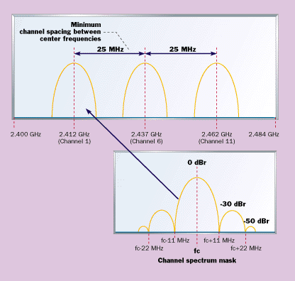
Barker word prior to transmission. DSSS systems operating in the 2.4-GHz band feature
channels that occupy 22 MHz of bandwidth. This channel bandwidth scheme
was chosen to allow three independent, non-interfering WLAN networks
across 83.5 MHz of spectrum. An example of the channel spacing and shaping
of the waveform for DSSS operation is illustrated in Figure 1 .
A new approach Top As the IEEE 802.11 committee began to look at higher
speed operation, it was clear that supporting interoperability with legacy
1- and 2-Mbps DSSS systems was extremely important, and changes to the
current DSSS channel scheme were not possible. The committee realized it
had to move toward a new modulation technique that would allow higher
speed operation without widening channel bandwidths.
During the evaluation process, the IEEE 802.11
committee considered a variety of modulation scheme proposals. These
proposals included M-ary bi-orthogonal keying (MBOK), quadrature amplitude
modulation (QAM), Barker code pulse position modulation (BCPM), packet
binary convolutional coding (PBCC), M parallel orthogonal spreading
signals, and carrier frequency offset spread spectrum.
After some heated battles, the committee adopted a
joint proposal put forward by Lucent and Intersil Corporation for the
802.11. Under this proposal, designers could achieve higher-speed
operation in DSSS WLAN systems using a complementary code keying (CCK)
modulation scheme. In addition to CCK, the committee adopted PBCC, a
modulation proposed by Alantro Communications as an option in the standard
for future applications requiring higher performance and robustness.
Systems implementing PBCC must support CCK to be interoperable with
802.11b 11-Mbps WLAN systems. A control bit is provided in the preamble
and PLCP header to indicate whether PBCC is supported.
More on CCK CCK was chosen over other modulations for
its superior performance when combating multipath. CCK is a form of vector
modulation and a variation of M-ary orthogonal keying (MOK) modulation
which uses I&Q modulation with complex symbol structures. The
spreading employed by CCK offers the same chipping rate and spectrum shape
as the legacy Barker word spreading functions as shown in Figure 1 . The
CCK modulation is not a new concept in the communication market. In fact,
this approach has been around for decades and is based on a complex code
set known as complementary codes. The origins of complementary codes date
back to the 1950s, when M.J.E. Golay conceived them for infrared multislit
spectrometry. Over the years, complementary codes found their way into
radar and communication applications for their rich autocorrelation and
cross-correlation properties. The IEEE committee drew on past complementary code
efforts to develop the CCK modulation scheme for the 802.11b spec. By
doing this, the committee developed a CCK scheme that uses complementary
codes derived from Walsh/Hadamard functions. Walsh/Hadamard functions are
similar to those used in cellular phone CDMA applications. They have
excellent complex code properties. Using complex codes, we can get a
larger set of orthogonal codes to select from and still get the same
number of bits transmitted per symbol. These codes, used together with
CCK, suffer less from multipath distortion in the form of cross coupling
of I&Q channel information. The spreading function for CCK was chosen from a set
of a "M" nearly orthogonal vector by the data word. CCK uses one vector
from a set of 64 complex (QPSK) vectors for the symbol, and thereby
modulates 6 bits (one of 64) on each 8-chip spreading code. Two additional
bits are sent by QPSK, modulating the entire code symbol and thus
modulating 8 bits onto each symbol. The net effect is a symbol that has 16
bits of complexity. Overall, the symbol rate for CCK is 1.375
Msamples/sec with a chipping rate of 11 Mchips/sec for 8 bits per symbol.
This translates into a data rate of 11 Mbps. The MAC layer was not the only important issue the
802.11 committee considered when developing the high-rate specification.
The committee also spent time working on the PHY preamble structure.
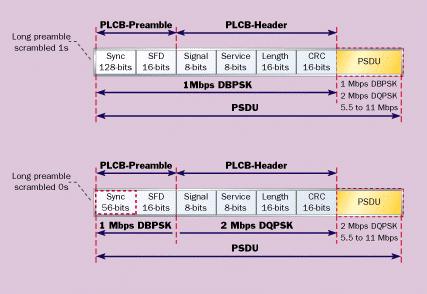
The IEEE 802.11b protocol supports data rates of 1,
2, 5.5, and 11 Mbps. To achieve such data rates, two PHY preamble header
structures are supported. These structures include a long and short
preamble (see Figure 2 ).
The long preamble uses the legacy 1- and 2-Mbps DSSS header to allow
interoperability with other legacy systems. The preamble consists of a
128-bit sync field containing a string of scramble logic 1s followed by a
16-bit start-of-frame (SFD) field. Acquisition of the received signal for
long preambles and headers are processed at 1 Mbps. Data packets contained
in the PLCP service data unit (PSDU) can be received at 1-Mbps-DBPSK,
2-Mbps-DQPSK, and 5.5- and 11-Mbps CCK. The rate at which the PSDU is
received is determined by the value stored in the signal field. To ensure
interoperability with legacy systems, all compliant 802.11b systems must
support the long preamble. The short preamble option was provided in the
standard to improve the efficiency of a network's throughput. The short
preamble uses a 56-bit sync field, which is scrambled with logic 0s,
followed by a 16-bit SFD field. The acquisition of the preamble signal is
processed at 1 Mbps. The header is processed at 2 Mbps and the payload in
the PSDU can be processed at 2, 5.5, or 11 Mbps. It takes a maximum of 192
ms to process the long preamble and 96 ms to process the short preamble.
The short preamble yields a 50% savings in overhead in a PLCP data unit
(PPDU) frame on a per packet basis. The short preamble can improve the
throughput of a network when transmitting control frames and fragmented
data packets carrying time-bounded content such as voice, VoIP, and
streaming video. |
|
Copyright(c)2000 CREWAVE CO.,Ltd. All rights reserved. |

