Protocol Engineering
-
The sequence chart is good at capturing the normal/specific
scenario of system interactions. It is difficult to show several/all possible
scenarios simultaneously on a chart and that often leads to ambiguity in
the specification.
-
Provide a formal and unambiguous way of designing
and documenting protocols.
-
Allow formal analysis (verification/validation/performance
analysis) before protocols are implemented.
-
Allow automatic and direct generation of executable
programs from the formal specification.
Specification Languages
-
Informal methods -- such as the sequence chart
-
Formal methods
State Transition Models
--Finite State Machines (FSM),
--Communicating FSM (CSFM),
--Petri nets
Programming Languages Models
--Abstract Programs
--CCS (Calculus of Communicating systems), CSP
--Temporal logic
Hybrid Models
--Extended FSM (EFSM)
-
Language Standards
--SDL (FSM + extensions)
--Estelle (EFSM + extended Pascal)
--LOTOS (CCS+ADT)
Communicating Finite State Machines (CFSM)
-
Protocol is described as a set of Communicating
Finite State Machines.
-
Each CFSM represents a component (or process) of
the network (in OSI term, a protocol entity, e.g. sender, receiver).
-
Each CFSM is represented by a directed labelled
graph where
--Nodes represent states (conditions) of the process;
--Edges represent transitions (events) of the process.
-
Transitions include actions taken the process (e.g.
the sending
a message) or external stimuli (e.g. the reception of a message).
-
The sending message transition is labelled as -Msg
where Msg is the type of messages being sent. The receiving message transition
is labelled as +Msg where Msg is the head message on the incoming FIFO
queue of the CFSM.
CFSM operating semantic
-
The channels that connect CFSM's are assumed to
be FIFO queues.
An error-prone channel is modelled as a CFSM.
-
Initial node--starting state of a CFSM.
Final node--no transition.
Receiving node--all (outgoing) transitions are receiving transitions.
If no
message or incorrect msg in the channel, the node will be blocked.
Sending node--all transitions are sending transitions. They are not
blocked.
Mix node--has both receiving and sending transition.
-
Starting at the initial node, a CFSM traverses the
nodes and transitions.
The node currently being visited is called the current node.
-
When a machine traverses a sending transition,
it sends/appends a message with the same label to its outgoing channel.
-
A machine at a node cannot traverse its receiving
transition unless there is a message matched with the same label on the
head of its incoming channel.
-
When a machine traverses a receiving transition,
it removes the matched head message of its incoming channel.
-
Among several possible transitions, a machine traverses
one non-deterministically
Networks of CFSMs
-
Example 1: Simple request-response protocol.
-
Example 2: What happens if we change the initial
node of a CFSM?
-
Example 3: An aggressive protocol with a self-sending
loop.
-
Example 4: A simple sliding window protocol with
a window size of 2.
CFSM Modeling Exercises
-
How to specify the channel behavior as a CFSM which
1) loses every other packet,
2) loses packets sometimes,
3) loses and corrupts the packet sometimes?
-
How to extend the model to specify CFSMs with the
multiple channels?
Pros and Cons of the CFSM model
-
CFSM deals only with the state-transition aspect
of protocols;
it does not address the data aspect of protocols, e.g., message content
or format.
-
It can not handle protocols where state variables
have a wide range of values.
Extended FSM were proposed but EFSM becomes difficult to analyze.
-
The FIFO channels assumption in CFSM is very powerful,
just think about how to model an unbounded or even a large buffer using
Petri net.
-
CFSM is an abstract model. The non-determinism
in the execution of transitions of a mix node may result in different implementation.
You can always expand the specification, e.g., replacing node 1 with a
subgraph.

The Alternating Bit Protocol as CFSMs
The Alternating Bit Protocol
is used to guarantee the correct data delivery between a sender and receiver
connected by an error channel that loses or corrupts messages.
It got
the name since it uses only one additional control bit in the message and
this control bit only alternates when the previous message is correctly
received.....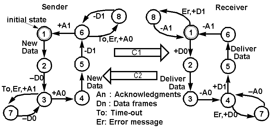
Verifying the Alternating Bit Protocol
Assume that C1 is the outgoing
channel of the sender and C2 is the outgoing
channel of the receiver. Let us
assume that C1 loses the odd numbered messages, i.e., the 1st, 3rd, 5th,
and so on, while C2 delivers every message.
Let S be the sender, R be the receiver,
and E stands for an empty channel.
Let the 4-tuple (sender state,
receiver state, C1 content, C2 content)
represent the global state, a snapshot
of the overall system state.
The following state transition
sequence illustrates that the
alternating bit protocol in page
8 is capable of delivering data without
duplication and in the right order.
(1,1,E,E)--S:NewData-->(2,1,E,E)
sender receives data, x, from its upper layer
(2,1,E,E)--S:-D0-->(3,1,D0,E) sender
attaches a sequence bit 0 after x. D=x
(3,1,D0,E)--C1:lose D0-->(3,1,E,E)
(3,1,E,E)--S:To-->(7,1,E,E)
(7,1,E,E)--S:-D0-->(3,1,D0,E) retransmit
D0
(3,1,D0,E)--R:+D0-->(3,2,E,E) This
time C1 correctly delivers the message.
(3,2,E,E)--R:DeliverDate-->(3,3,E,E)
receiver delivers x to its upper layer
(3,3,E,E)--R:-A0-->(3,4,E,A0)
(3,4,E,A0)--S:+A0-->(4,4,E,E)
(4,4,E,E)--S:NewData-->(5,4,E,E)
sender receives data, y, from its upper layer
(5,4,E,E)--S:-D1-->(6,4,D1,E) sender
attaches a sequence bit 1 after y. D=y
(6,4,D1,E)--C1:lose D1-->(6,4,E,E)
this is the third message received by C1
(6,4,E,E)--S:To-->(8,4,E,E)
(8,4,E,E)--S:-D1-->(6,4,D1,E) retransmit
D1
(6,4,D1,E)--R:+D1-->(6,5,E,E) This
is the fourth msg. C1 delivers it.
(6,5,E,E)--R:DeliverData-->(6,6,E,E)
receiver delivers y to its upper layer
(6,6,E,E)--R:-A1-->(6,1,E,A1)
(6,1,E,A1)--S:+A1-->(1,1,E,E)
Note that the message sequence
xy from the upper layer of the sender is correctly delivered to the upper
layer of the receiver.
Protocol Verification using Reachability Analysis
Reachability Analysis
-
It is a global state exploration process that starts
from the initial global state and recursively explores all the possible
transitions that lead to new global states. The result is a reachability
graph, which captures all possible states.
Protocol Design Errors
-
Unspecified reception--at receiving/final nodes,
head msg transition labels.
What happens if you throw away those head msgs that are not specified?
-
Deadlock--both at receiving nodes, no msg in channels.
-
Livelock=processes keep exchanging messages but
not making "effective progress".
need to mark transitions as either effective-progress or non-effective-progress
and then check if there exist cycles in the reachability graph whose constituent
transitions are all non-effective-progress.
-
State ambiguity--global states with the same process
states but different channel status. (This is a potential error, may not
be a real one.)
-
Channel buffer overflow. Give the simplest protocol
example.
-
Non-executable transitions--dead code. How do you
detect that?
Protocol Verification Exercises
-
What are the channel buffer sizes needed for the
following two machines?
-
Will the following situation considered to lead
to an unspecified reception?
More Exercise on Reachability Analysis
-
Find deadlock, unspecified reception global states
in the following protocol
-
There are also non-executable transitions and nodes
in the two CFSMs.
-
How many buffers are required in each of the two
channel?
-
I will give you the reachability graph and answer
next time.
Pros and Cons of Reachability Analysis
-
Easily automated.
-
Many logical errors can be detected by only examining
individual global states in the reachability graph.
Disadvantages:
-
State space explosion problem.
-
Does not work on unbounded protocols.
-
Many relationships among the protocol state variables,
expressing the desirable logical correctness properties of the protocol,
are not apparent from simply traversing the reachability graph.
Tools for specification development
-
CFSM--S-IBM-Zurich, PROSPEC
-
Petri net--P-nut, PROTEAN
-
SDL-- SDL-PR-GR, SDL-SDT
-
EFSM--spanner
-
Lotos--Sedos, Ottowa
-
Estelle--NBS,Sedos,UBC
I have ported the state exploration
tool of PROSPEC to X window system.
It is called setool.
-
To use the setool, include /users/server/students/cs522/bin
in your path environment variable.
-
The man page is in /users/server/students/cs522/tools/se/man/man1/setool.1
You can include /users/server/students/cs522/tools/se/man in your manpath
-
There are some protocol examples in /users/server/students/cs522/tools/se/examples.
-
You can use the setool to verify your answers to
the homework and exercises.
Homework #2
Exercise 1. Reachability Analysis.
Given the following network of two communicating finite state machines,
a) Perform the reachability analysis on the Network (M, N).
b) What sizes of buffers are needed for the two FIFO channels?
c) Are there non-executable states or transitions?
Exercise 2. Describe the event
sequence (starting from initial states) of the alternating bit protocol,
if both channels lose every other message (it loses the 1st, 3rd, 5th,...
messages it received)? Each event can be identified as <machine, src-state,
dst-state, msglabel> or <channel, lost msg | deliver msg> Include events
up to the one that successfully delivers A1.